
|
The importance of proper ventilation in health care facilities cannot be overemphasized. HVAC design for health care facilities is all about providing a safer environment for patients and staff. This design differs from that of the conventional HVAC systems used in other building types.
These requirements demand very high quantities of outside air along with significant treatment of this ventilation air, including cooling, dehumidifying, reheating, humidifying, and filtration. HVAC particularly helps in controlling infection and contaminants in a healthcare setting.
The most effective means of controlling Infection, contaminants, odor, and indoor air pollution is through ventilation, which requires simultaneous control of a number of conditions:
Increasing ventilation rate is believed to reduce the cross-infection of airborne transmitted diseases by removing or diluting pathogen-laden airborne droplet nuclei. A higher ventilation rate can dilute the contaminated air inside the space more rapidly and decrease the risk of cross-infection.
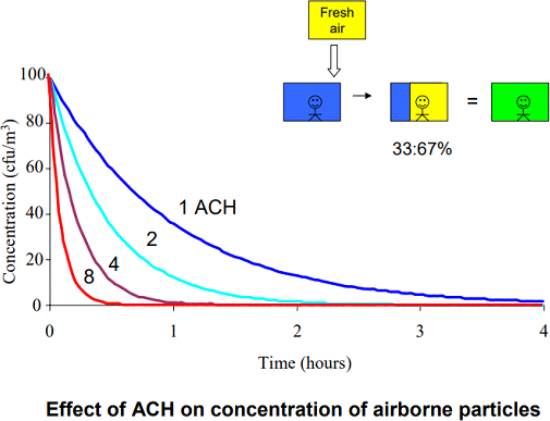
Figure 1: Effect of Air Change per Hour on the Concentration of Airborne particles
A higher ventilation rate is able to provide a higher dilution capability to reduce the cross-infection. The use of higher ventilation rates also means a higher energy cost for mechanical ventilation. However, the recommended minimum ventilation rate for airborne infection isolation rooms is 12 air changes per hour (ACH).
Natural ventilation is able to deliver large ventilation rates with low energy consumption. Compared with mechanical ventilation, natural ventilation can provide much higher ventilation rates The American Society of Heating, Refrigerating, and Air-Conditioning Engineers (ASHRAE) is recognized as the world leader in establishing standards and training for the design of HVAC systems. The standards most frequently used in healthcare engineering are:
Table 1. Standard 170 room requirements
The infected patient can contaminate the environment. A single room with appropriate air handling and ventilation prevents direct or indirect contact transmission. It also reduces the risk of airborne transmission of microorganisms from a source patient to susceptible patients and other persons in hospitals. This is often termed “Isolation Room” in medical terminology.
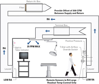
Figure 2: Graphical presentation of a protective environment
The differentiating factor between “AII” and “PE” rooms is the pressure relationships.
”PE” room is Positive pressure room & “All” room is Negative pressure room
⦁ POSITIVE PRESSURE ISOLATION ROOMS
Class P – positive pressure isolation rooms are set at positive pressure relative to ambient pressure, meaning that airflow must be from the “cleaner” area towards the adjoining space (through doors or other openings). This is achieved by the HVAC system providing more air into the “cleaner” space than is mechanically removed from that same space.
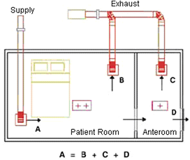
Figure 3: Positive Pressure Isolation Room
In the schematic diagram above, an airlock or anteroom is provided adjacent to the patient room. For a positive pressure room, air would flow from the isolation room to the anteroom and then to the corridor. Pressure control is maintained by modulating the main supply and exhaust dampers based on a signal from a pressure transducer located inside the isolation room.
⦁ NEGATIVE PRESSURE ISOLATION ROOMS
The basic principle of pressurization for microbial contaminant control is to ensure that air flows from less contaminated to more contaminated areas. The air in an open Class N room, for example, should flow from corridors INTO the isolation room to prevent the spread of airborne contaminants from the isolation room to other areas. The purpose of this design is to eliminate the spread of infectious contaminants and pathogens into the surrounding environment via the airborne route.
Class N is applicable to all infection isolation rooms where the patients known to or suspected to have infections are placed.
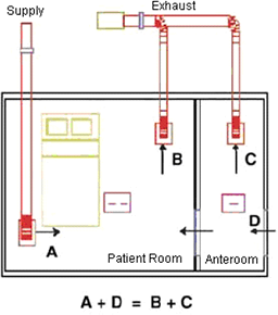
Figure 4: Negative Pressure Isolation Room
The schematic above shows the HVAC airflow arrangement for class N rooms. An anteroom designed to provide an “airlock” (no mix of air) between the infectious patient and the common space is placed adjacent to the patient room. The air would flow from the anteroom to the isolation room. Pressure control is maintained by modulating the main supply and exhaust dampers based on a signal from a pressure transducer located inside the isolation room.
For the critical areas such as isolation rooms, intensive care units, and operating rooms, critical diagnostic and examination rooms, consider only the centralized HVAC system encompassing “all air systems.”
All air systems can be classified as single-zone, multi-zone, dual-duct, and reheat systems.
Single-zone systems: Single-zone systems serve just one zone having unique requirements of temperature, humidity, and pressure.
Figure 5: Single Zone System
For this type of system to work properly, the load must be uniform all through the space, or else there may be a large temperature variation.
Multi-zone systems: Multi-zone systems are used to serve a small number of zones with just one central air handling unit. The air handling unit for multi-zone systems is made up of heating and cooling coils in parallel to get a hot deck and a cold deck
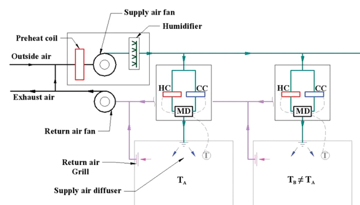
Figure 6: Multi-Zone System
Zone thermostats control mixing dampers to give each zone the right supply temperature.
Dual-duct systems: Dual-duct systems are much like multi-zone systems, but instead of mixing the hot and cold air at the air handling unit, the hot and cold air are both brought by ducts to each zone, where they are then mixed to meet the needs of the zone.
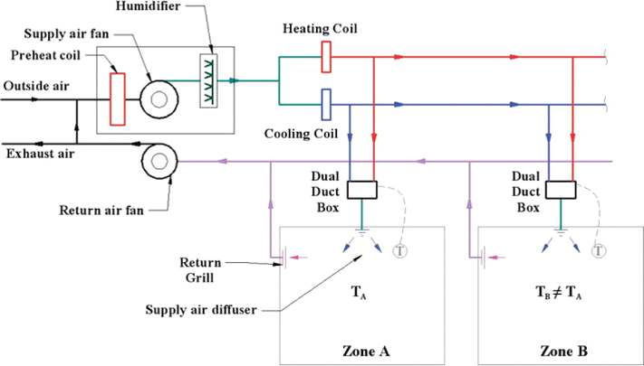
Figure 7: Dual Duct Zone System
It is common for dual-duct systems to use high-pressure air distribution systems with the pressure reduced in the mixing box at each zone.
Reheat systems: Reheat systems supply cool air from a central air handler as required to meet the maximum cooling load in each zone.
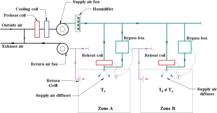
Figure 8: Reheat System
Each zone has a heater in its duct that reheats the supply air as needed to maintain space temperatures. Reheat systems are quite energy-inefficient
For the patient bedrooms and other non-critical areas, any one of the following HVAC systems can be used:
The amount of outdoor air and how it is supplied to the occupied spaces would depend upon the type of HVAC system used. When the fan coil units or radiant ceiling panels are used, a central ventilation unit supplies conditioned air to the spaces. With this arrangement, the source of outdoor air being external to the principle cooling and heating equipment, it is possible to ensure the predetermined amount of outdoor air distribution to all the spaces.
There are four main factors that affect the local concentration around a person in a room. These are:
Building room pressurization is a critical factor to monitor in a hospital as it can greatly affect the controllability of the environment. If the building pressure is allowed to become negative due to supply filters being loaded, supply fans running too slow, or return fans running too fast, humid and dirty air can be drawn into the building through cracks and openings. This air is completely unconditioned and can provide several of the necessary ingredients to promote mold growth (e.g., moisture, more spores, and nutrients.)
Building room pressure gradient is achieved by controlling the quality and quantity of intake and exhaust air, maintaining differential air pressures between adjacent areas, and designing patterns of airflow for particular clinical purposes.
Dynamic pressure differential monitoring must take place in order to ensure the room is at the appropriate pressure. The two common methods of differential pressure control are
1) Flow tracking measurement & control and
2) Differential pressure measurement & control.
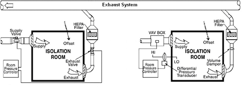
Figure 9: Flow Tracking Measurement & control Figure 10: Differential Measurement & control
Inflow tracking system, the exhaust, and supply flow rates “from” and “to” space are measured and controlled to produce a desired infiltration or exfiltration.
In a differential pressure system, the actual differential pressure between the isolation room and the corridor is taken by measuring the velocity of air induced through a hole in the envelope between the isolation room and corridor created by the differential pressure.
The design principle of pressurization control is to exhaust air from those areas which have the greatest contamination potential and allow air to be staged, or cascaded, from progressively cleaner areas. The figure below illustrates the basic principle of cascading airflows from clean areas to relatively contaminated areas.
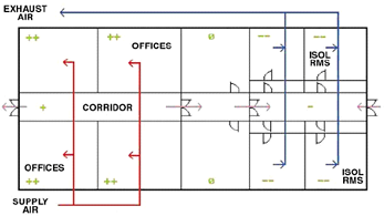
Figure 11: Differential Airflow for Isolation Room
In the above diagram, a facility is depicted which has offices and isolation rooms, separated by corridors and other areas (storage rooms, labs). Air is supplied to the areas, usually in offices, maintained at the greatest positive pressure (marked with a ‘++’), and exhausted from the areas maintained at the greatest negative pressure (marked with a ‘- -‘). Transfer air (exfiltration/infiltration) is identified with blue arrows.
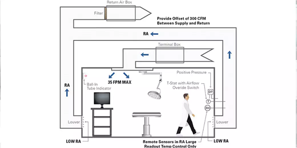
In health care facilities (e.g., operating rooms, delivery rooms, catheterization laboratories, angiography rooms, HEPA-filtered rooms for immune-suppressed patients), the direction of air movement needs to be controlled. The air is introduced from ceiling registers on the perimeter and is returned or exhausted through registers located at least 6 inches above the floor. This arrangement provides a downward movement of clean air through the breathing and working zones to the contaminated floor area for exhaust.
The figure below shows the introduction of low-velocity air near the ceiling at the entrance of the room, flowing past the patient, and exhausted or returned close to the floor at the head of the patient bed. An airflow pattern is thus established, which helps to move microorganisms from the point of patient’s expulsion to the exhaust/return air terminal to prevent health care workers or visitors from inhaling the bacteria.
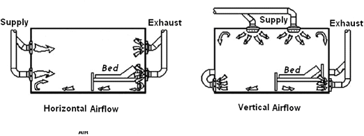
Figure 12: Room Air Distribution in the Isolation Room
Non-aspirating diffusers (typically perforated face) are recommended. These diffusers entrain large amounts of air, achieve good mixing, prevent updrafts, and provide a laminar flow of air that will flush the isolation room of unwanted airborne particles.
The diffuser should be placed away from the patient’s bed, preferably near the point where a health care worker or visitor would enter the room.
High-Efficiency Particulate Air (HEPA) Filters
HEPA filters have a minimum initial efficiency of 99.97% for removing particles 0.3 microns in size. This is a critical point as these filters are being used to remove mold and bacteria, typically 1 to 5 microns in size when airborne, as well as viral particles which are submicron in size
HEPA filters should be used:-
Two essential components of conditioned air are temperature and humidity. After outside air passes through a low – or medium-efficiency filter, the air undergoes conditioning for temperature and humidity control.
Control of temperature includes the operation of both heating and cooling systems to maintain temperature set points in the different areas of the building. Cool temperatures (68°F – 73°F) are usually associated with operating rooms, clean workrooms, and endoscopies suites. A warmer temperature (75°F) is needed in areas requiring greater degrees of patient comfort. Most other zones use a temperature range of 70°F – 75°F.
Temperatures outside of these ranges may be needed on limited occasions in limited areas depending on individual circumstances during patient care.
HVAC systems in healthcare facilities have either single-duct or dual-duct systems. A single-duct system distributes cooled air (55°F) throughout the building and uses thermostatically controlled reheat boxes located in the terminal ductwork to warm the air for individual or multiple rooms.
Efforts to limit excess humidity and moisture in the infrastructure and on-air stream surfaces in the HVAC system can minimize the proliferation and dispersion of fungal spores and waterborne bacteria throughout the indoor air. Control of humidity includes the operation of both humidification and dehumidification systems to maintain a minimum and maximum humidity level in the facility.
3S MEP + S provides integrated MEP, Fire Protection, Fire Alarm, BIM, Energy Modeling, and Structural Engineering services for building projects.
.png)
